
Resistance
Welding Controller
Resistance
Welding Controller
|
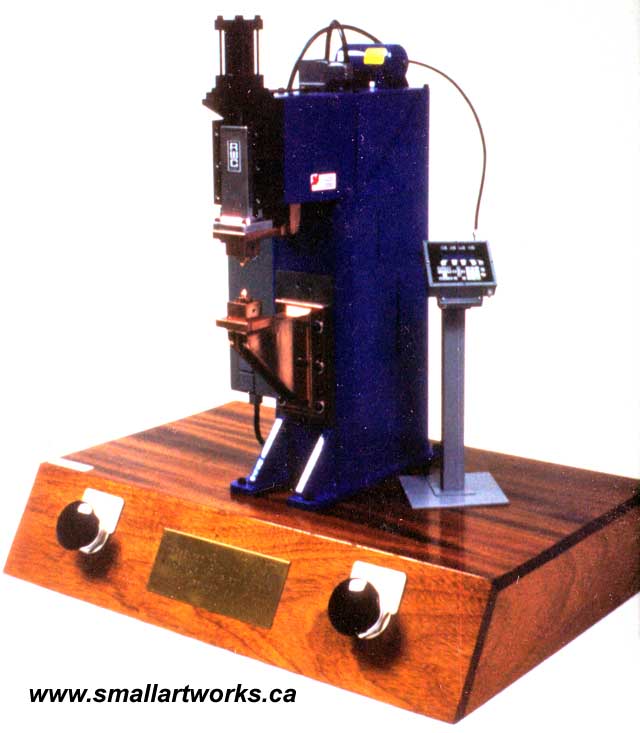
This is a 1/6th scale model of an electric welding unit that was built by someone many years ago for the president of the company I worked for (as a draughtsman/illustrator) in the late 1980's called Medar Canada Ltd., which is now defunct. The parent American company, Medar Inc., is still in business, but have recently sold their welding division. Medar made computer controlled welding units for use with spot welding machines for the big automotive manufacturers like GM, Ford and Chrysler. The model, which originally consisted of the wooden base, switches (which make the welder operate and simulate an electric spark... the thing was actually capable of spot-welding tin foil!) and the main unit on top (made of steel and copper) was somewhat dirty and needed a new paint job (it had been originally painted an industrial green colour) and a good deal of cleanup work done. Lawrence Alexander, the president of the company, asked me to refurbish the model of the welder itself and also wanted a replica of one of their newest control units attached to it, not originally on the model, in the highest amount of detail possible. This included the Data Entry Panel (the box and pedestal to the right of the welder) and the main controller unit itself (the gray box on the left side of the welder). I was to scratch build these additional units. I began by refurbishing the welder itself, so it was disassembled, thoroughly cleaned up and re-painted in royal blue, Medar's official company colour. Some extra panels, hoses and wiring were also added. The copper sections were cleaned, polished and coated with clear lacquer to preserve the finish. The fact that we built the actual controller units themselves right there at the shop made finding reference to build the models of them a no-brainer. Nothing beats having the real one in front of you while you build the model, plus I had already done several technical drawings of the unit already (click HERE to see one of them). It was quite a simple matter to work out the scale. Then, component by component, after thousands of measurements, the models were built accurately down to the last detail, including all nuts, bolts and screws. Even the wiring inside was made to go exactly where it was supposed to! The highly detailed models were made mostly from styrene plastic sheet, but occasionally I would use found objects, modified to precisely resemble certain parts and sections. Even labels and serial number tags on the various components were made completely from scratch in precise 1/6th scale, entirely by hand. Keep in mind that this was before the days of affordable scanners and Photoshop, so digital printouts and custom decals were not possible to do! Some labels that are just simple black and white, such as the main label on the front of the door, was made by reducing the real one on a photocopier and cemented to a thin plastic sheet. The tiny manual and blueprint seen inside the door pocket (included with the real units we sold) were made that way, but the blueprint was then finished by running that photocopy through a diazo printing machine, making a truly authentic blueprint at 1/6th scale! The models were
painted using Tamiya Acrylics, mostly custom mixed to match the exact colours
of the original. The "powder-paint" texture seen on the full scale unit
was simulated by dabbing the paint on with a fine sponge rather than spraying
it on. The wiring was made from very fine wire, all hand painted with the
correct colours to match the real one. Everything else is completely made
from scratch. It took approximately six weeks to build this extremely detailed
model during the year 1987.
|
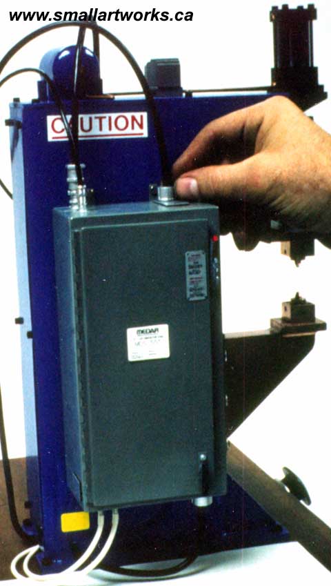
A co-worker's hand gives an idea
of the scale of the model.
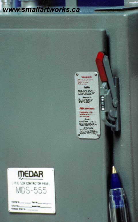
Two labels on the front of the door.
The white one is a reduced photocopy of the real one, the tall label is
a hand made replica of an aluminum panel. The breaker switch at right actually
works, and is exactly to scale. A common BIC pen is placed for reference.
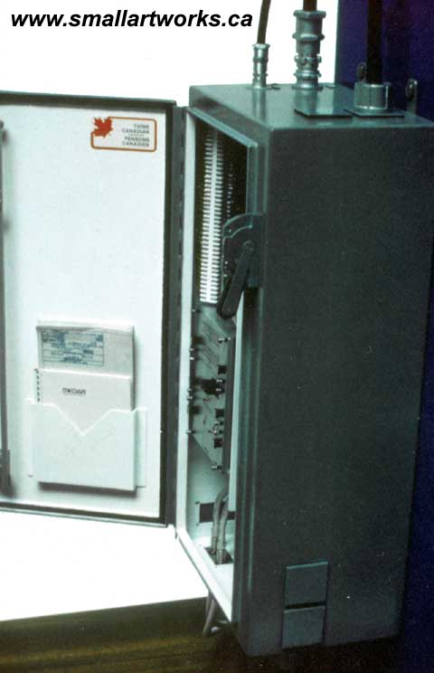
Note the manual and blueprint inside
the door pocket. The functioning main latch mechanism and weather stripping
around the inside of the door are also faithfully reproduced.
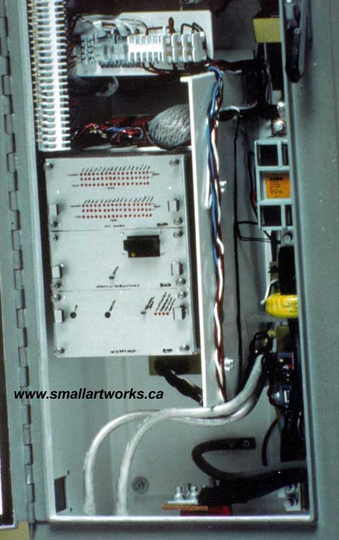
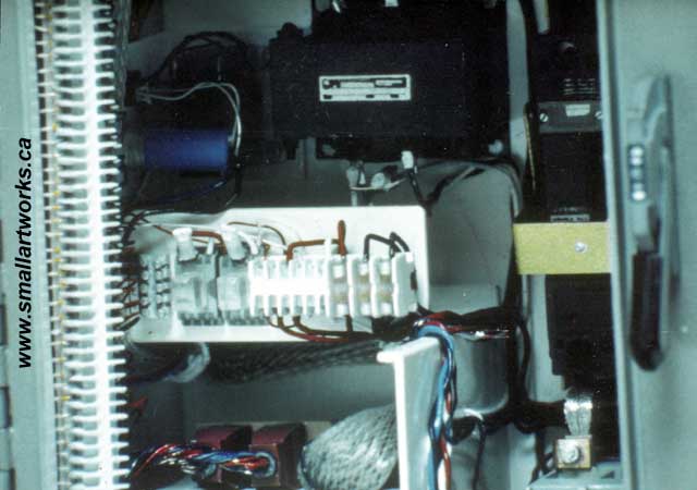
The "guts" of the main unit, revealed
upon opening the door. Even the functioning hinges are exactly to scale
and completely scratch built.
The silver box in the lower left
of the above photo is made from brushed sheet aluminum, just like the real
one. Details, like the thumbscrews, were made by turning and polishing
nail heads chucked in a Dremel tool, other bits made from plastic and aluminum.
The flat silver cables leading from the main breaker to the isolation contactor
at right is made from de-soldering braid. Real copper was used for the
connectors.
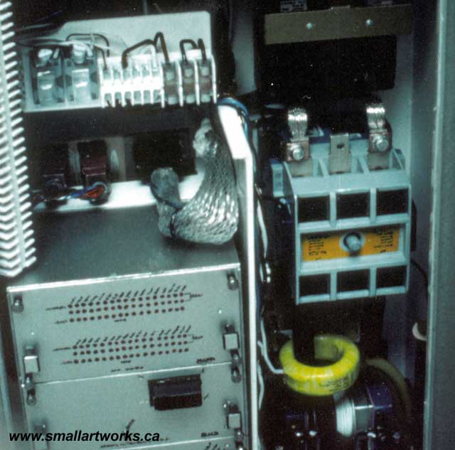
The ladder-like fuse strips
at left and in the centre of the above picture were also scratch built,
with tiny wires and simulated screws, all wires leading to their correct
locations within the unit.
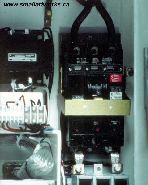
The gold breaker switch plate moved
and actually operated the breaker switch, which was properly spring loaded.
The big black breaker switch itself is made from sheet styrene, with clear
plastic lens and hand painted labels. The tiny fuses at left were made
from pieces of clear plastic to simulate the glass on the real fuses.
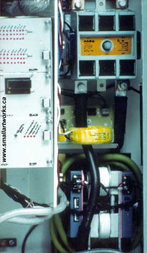
The Isolation Contactor, made from
sheet styrene, is shown at top right. The yellow ring in the centre is
made to resemble a coil of wire wrapped in tape which is fastened to a
printed circuit board. All components are faithfully reproduced. The SCR
(Silicon Controlled Rectifier) with it's coil of cooling hoses is shown
at the bottom.
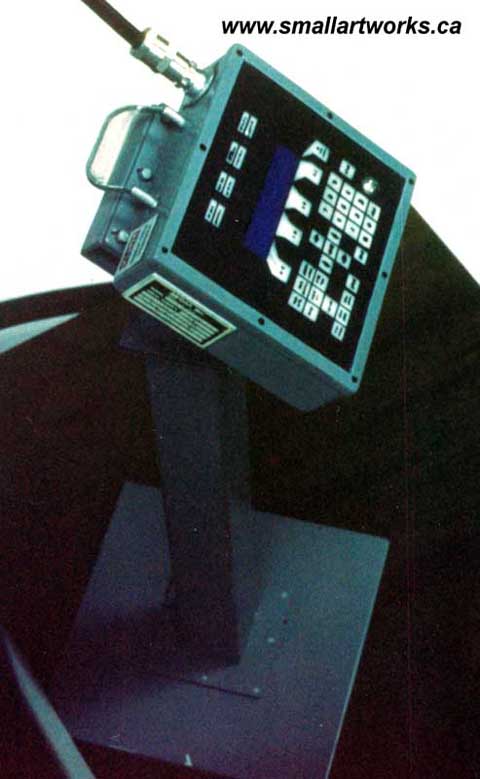
The Data Entry Panel on it's pedestal.
This piece is about an inch and a half square. Clear cellophane simulates
the touch pad on the face. Identification plates were made by reducing
real ones on a photocopier and mounting them to plastic sheet.
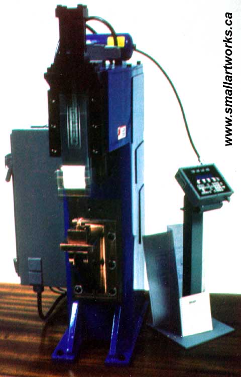
A time exposure photo shows the
movement of the welding head and the resulting spark. Note the tiny scale
manual and "blueprint" at the base of the D.E.P. pedestal.